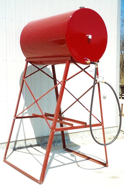
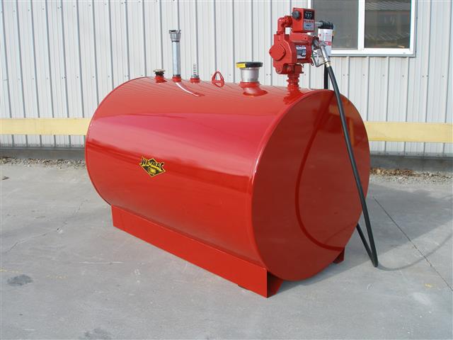
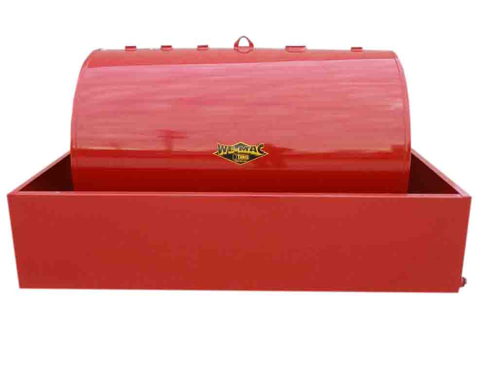
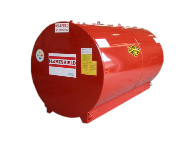
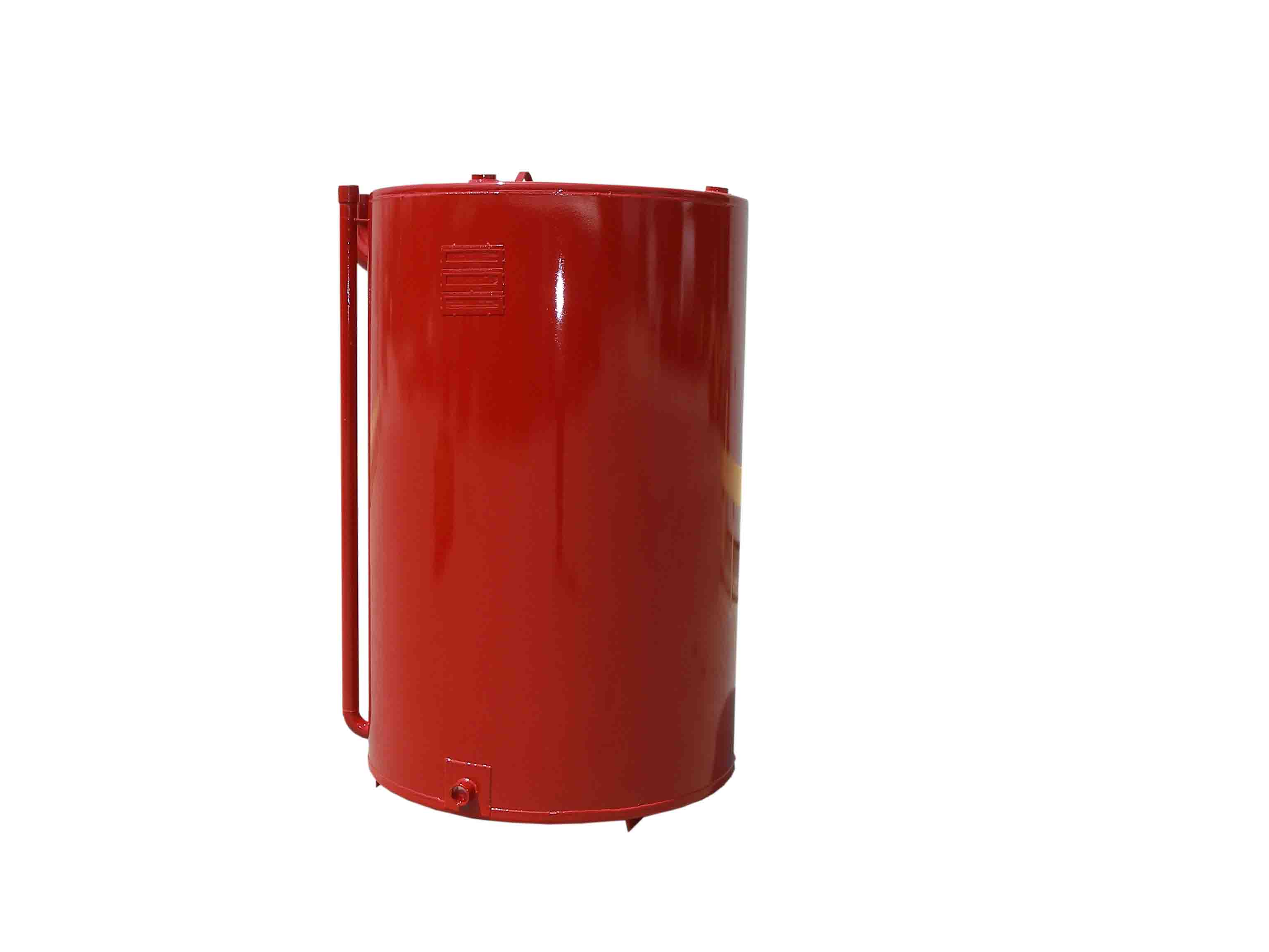
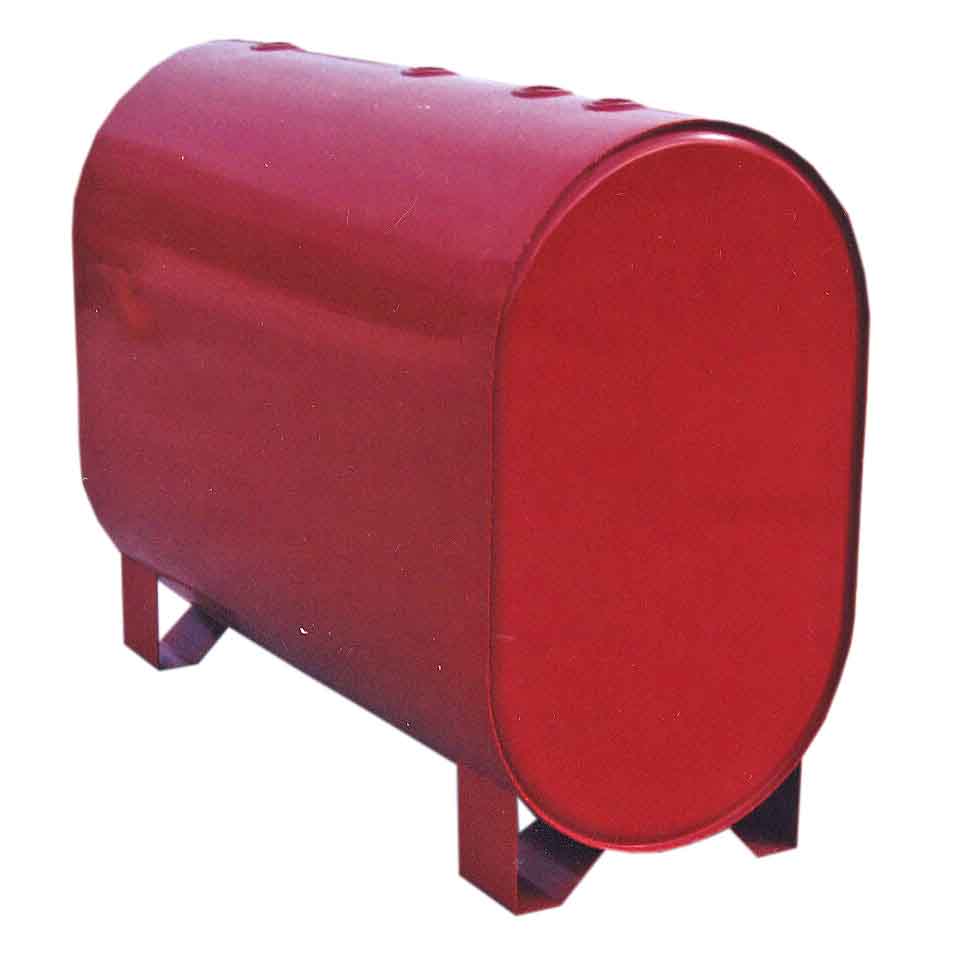
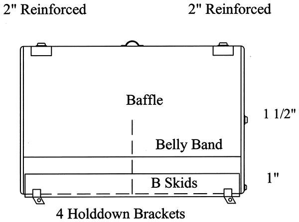
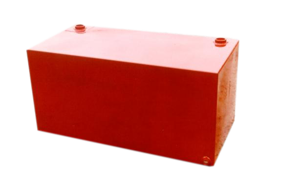
We-Mac Manufacturing, Inc.
(Permission to copy is granted by WeMac, Inc.)
UNDERGROUND
OIL/WATER SEPARATOR
Specification
PART 1- REFERENCES
The publications listed below form a part of this specification to the extent referenced. The
publications are referenced too in the text by basic designation only.
- 1.1 American Petroleum Institute (API)
- API Publication 421, "Monographs on Refinery Environment Control - Management of Water
Discharges, Design and Operation of Oil-Water Separators."
- 1.2 American Welding Society (AWS) Standards
- D1.1-92 Structural Welding Code-Steel.
- 1.3 Underwriters Laboratories, Inc. (UL) Publication
- UL 58 Standards for Safety - Steel Underground Tanks for Flammable and Combustible Liquids.
- 1.4 Steel Tank Institute (sti) Standards:
- Publication #F894-91 - ACT - 100 Specification for External Corrosion Protection of FRP
Composite Steel Underground Storage Tanks
Permatank
Sti-P, Corrosion Control System
Total Containment
- 1.5 American Society for Testing and Materials (ASTM) Standards:
- A36-93 Structural Steel
- 1.6 American national Standards Institute (ANSI) Standards:
- ANSI B16.5-88 Pipe Flanges and Flanged Fittings
- 1.7 EPA Methods for Chemical Analysis of Water & Wastewater
- 16th Edition (1985) -Section 503A
- 1.8 Steel Structures Painting Council (SSPC) Standards:
- SSPC-SP10 Near-White Blast Cleaning
PART 2 - GENERAL
- 2.1 Application
- The oil/water separator shall be a prefabricated cylindrical unit of the parallel corrugated plate
gravity displacement type as specified herein and as described in API Publication 421. The
oil/water separator shall be designed for gravity separation of non-emulsified oil from the waste
water stream only along with some settleable solids. The source of the influent to the separator
shall be gravity flow from storm water runoff or process operations.
- 2.2 Performance
- The separator shall remove essentially all free and dispersed non-emulsified oil from the water
stream and produce an effluent containing less than __ mg/l of oil droplets larger then __
microns.
- 2.3 Influent Characteristics:
- Provide oil/water separator designed for a maximum average flow of __ gallons per minute
(gpm). The influent is further characterized as follows:
Operating Temperature __ F
Specific Gravity of Oil __
Specific Gravity of Water __
Specific Gravity of Solids __
- 2.4 Design Criteria
- The oil/water separator shall be designed in accordance with Stokes Law and API Bulletin No.
421. Design Reynolds number not to exceed 500.
- 2.5 Inspection and Quality Assurance
- The oil/water separator shall be fabricated, inspected and tested for leakage before shipment from
the factory as a completely assembled system ready for installation.
- 2.6 Submittals
- Shop drawings for separators shall be submitted and shall show principal dimensions and
locations of all fittings. Design calculations shall be provided and shall reflect that oil/water
separator is in conformance with effluent requirements when operation under detailed influent
conditions. These calculations should show oil rise rate, overflow rate, Reynolds Number an
removal efficiency. Shop drawings shall include brochures, catalog cuts, operations and
maintenance instructions, dimensions, and location of accessories.
- 2.7 Design Data
- Submit analysis (signed by a registered Professional Engineer) which indicates that at the
calculated overflow rate, the separator will be provided with the required square feet of projected
plate separation area to achieve the specified performance under laminar flow (i.e. Reynolds
number of less than 500) conditions. Calculations shall take into account the rate of flow,
potential surge flow, influent concentrations, particle characteristics, fluid temperature, fluid
specific gravities, and pH.
PART 3 - CONSTRUCTION
- 3.1 Fabrication
- Manufacturer shall be a licensed sti and TES member. Provide a special purpose prefabricated
parallel corrugated plate cylindrical gravity displacement type (single wall, double wall type I,
double wall type II) oil/water separator. The separator capacities, dimensions, construction, and
thickness shall be in strict accordance with UL 58. Separator shall be comprised of a tank
containing an inlet compartment, separation chamber, oil storage chamber, sludge chamber and
clean water outlet chamber.
- 3.2 Tank
- The tank shall be constructed of __" minimum thick carbon steel plate conforming to ASTM
A36. Weld in accordance with AWS D1.1 to provide a watertight tank that will not warp or
deform under load. Pipe connections to the exterior shall be as follows:
| Description | Qty | Size | Type Connection |
| Separator Inlet | 1 | [A/R] | 150# Flange |
| Clean Water Outlet  | 1 | [AR] | 150# Flange |
| Oil Pump Out | 1 | 4" | 150# Flange |
| Gauging | 1 | 2" | NPT |
Tank Vent | [AR] | [AR] | NPT |
- 3.3 Flanges
- Use only flat face flanges and drill 150 pound ANSI standard bolt circle. Use flanged
connections that conform to ANSI B16.5.
- 3.4 Manways
- Mayways provide access into the separator. Each manway will be provided complete with
extension, bolt down cover, gasket, and bolts.
- 3.5 Lifting Lugs
- The tank shall be provided with properly sized lifting lugs for handling and installation.
- 3.6 Labeling
- Labels shall include UL 58, Sti, and TES
- 3.7 Identification Plates
- Identification plate should identify manufacturer, describe procedures for operating and servicing
the equipment, and include warning of any hazardous conditions. Plates shall be durable and
legible throughout the life of the equipment.
- 3.8 Inlet Compartment
- The inlet connection chamber shall have a spirex inlet pipe to distribute the flow across the
width of the separation chamber. The inlet compartment shall be of sufficient volume to
effectively reduce influent suspended solids, dissipate energy and begin separation. A sludge
baffle will be provided to retain settleable solids and sediment from entering the separation
chamber.
- 3.9 Separation Chamber
- Provide an oil separator chamber containing parallel plates. Parallel plates shall be at an angle
from 40 to 60 degrees with respect to longitudinal axis of the plate corrugations and spaced not
less than inch and not more than 1-1/8 inch apart for removal of free oil and settleable solids.
Configuration used shall not promote solids buildup on plates, which would increase velocities to
point of discharging an effluent of unacceptable quality. Maintain laminar flow (i.e. Reynolds
number of less than 500) at maximum design flow rate throughout plate packs including entrance
and exit so as to prevent re-entrainment of oil(s) with water. Flow through plate packs shall be in
a downflow mode parallel to plate corrugations or cross-flow perpendicular to plate corrugations
and rises to top of pack without clogging from oil or settleable solids.
- 3.10 Sludge Chamber
- The sludge chamber shall be located under the separation chamber and shall provide an adequate
volume for the setting of any solids. It shall also prevent any solids from entering the clean water
chamber.
- 3.11 Oil Reservoir
- The waste oil storage shall be an integral part of the separator, and have a capacity of 50 percent
of the total separator volume. Oil will flow from the separator by gravity or can be pumped away
when the oil/water interface reaches a predetermined depth.
- 3.12 Clean Water Chamber
- Provide clean water chamber which allows the water to leave the separator by gravity flow
through the clean water outlet flange.
- 3.13 Vents and Hold Down Straps
- Sufficient vents and hold down straps shall be provided.
- 3.14 Corrosion Protection System:
- Oil/water separator corrosion control system shall be in accordance with Steel Tank Institute
specifications as applied by a licensee of the Steel Tank Institute. The corrosion control system
shall be comprised of one of the following:
ACT-100: 100 mill scratch resistant FRP laminate bonded to outlet tank wall
sti-P3: 15 mils polyurethane exterior coating and sacrificial anodes
- 3.15 Interior Coating
- Interior surfaces shall be sandblasted in accordance with SSPC-SP10 and coated with:
Tnemec Series 61 liner to 10 mils DFT or equal.
PART 4 - ACCESSORIES AND OPTIONS
- 4.1 Oil/Water Separator Accessories
- The manufacturer shall provide the following accessories as part of the oil/water separator.
- 4.2 Removable Polypropylene Coalescer
- The manufacturer shall provide a removable polypropylene coalescer designed to intercept oil
globules of not less than 20 micron in diameter to an effluent quality of 10 mg/l free petroleum
hydrocarbon.
- 4.3 Sampling Ports
- Sample ports shall permit easy access for obtaining isokinetic samples. Sample ports shall
consist of a short length of " diameter ball valve, and another short length of " diameter
tubing on the outlet of the ball valve.
PART 5 - WARRANTY
- 5.1 Oil/water separator tank
- The oil/water separator tank shall be provided with a 30 year Steel Tank Institute warranty
against corrosion.
- 5.2 Oil/water separator accessories
- All accessories and treatment equipment supplied as part of the oil/water separator system shall
contain a one (1) year warranty for defective equipment.
For the Engineering Data Sheet
For more information
We-Mac Manufacturing, Inc.'s Home Page